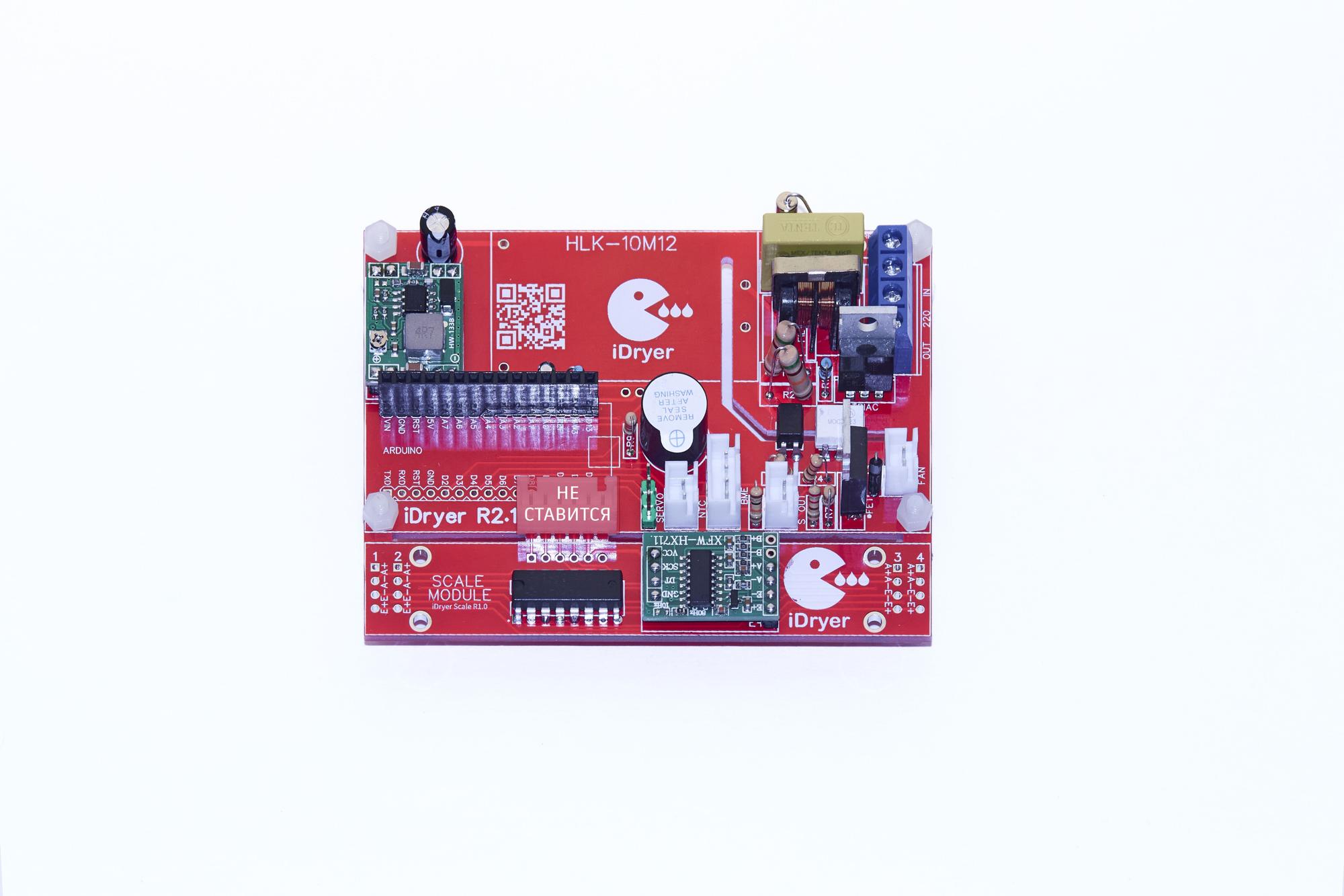
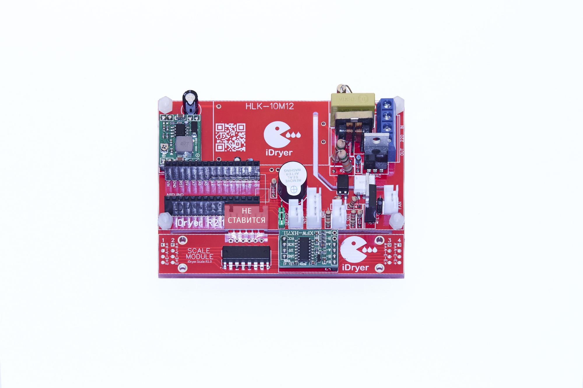
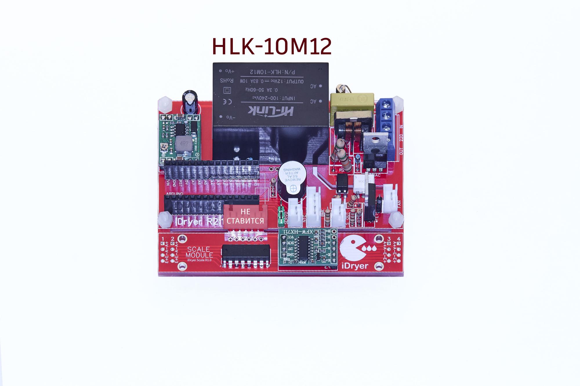
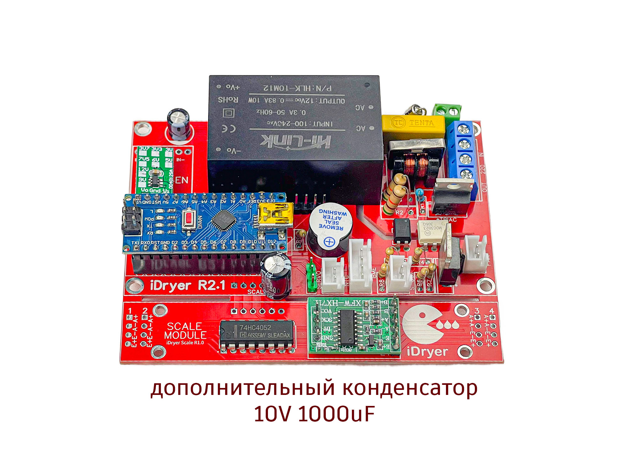
Controller r2.1 Assembly Instructions
Following a simple sequence of steps, you can have a fully assembled device in approximately 40-60 minutes. You will need the following tools and materials:
- multimeter
- soldering iron
- solder
- soldering paste/rosin
- wire cutters/diagonal pliers
- isopropyl alcohol for cleaning the board after soldering
- small brush (e.g., toothbrush) for cleaning the board after soldering
- it is convenient to have a "third hand" or vise
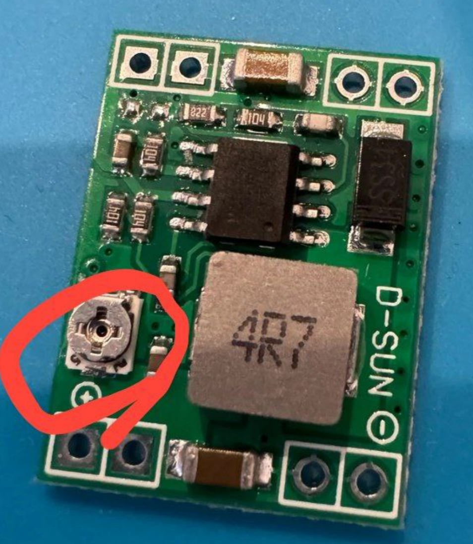
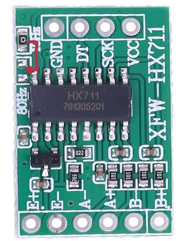
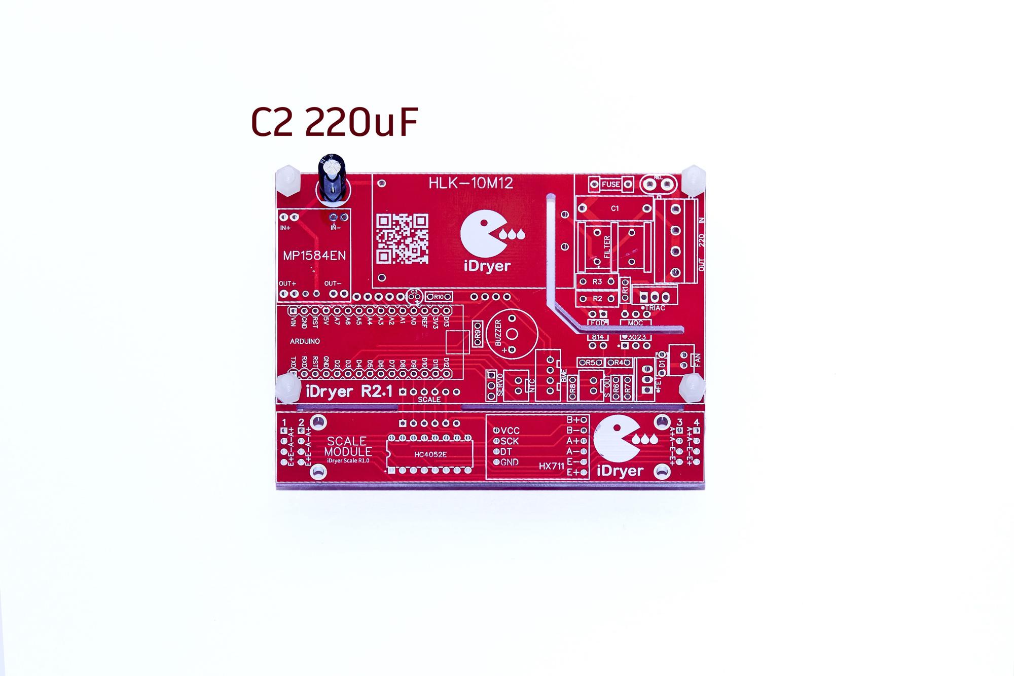
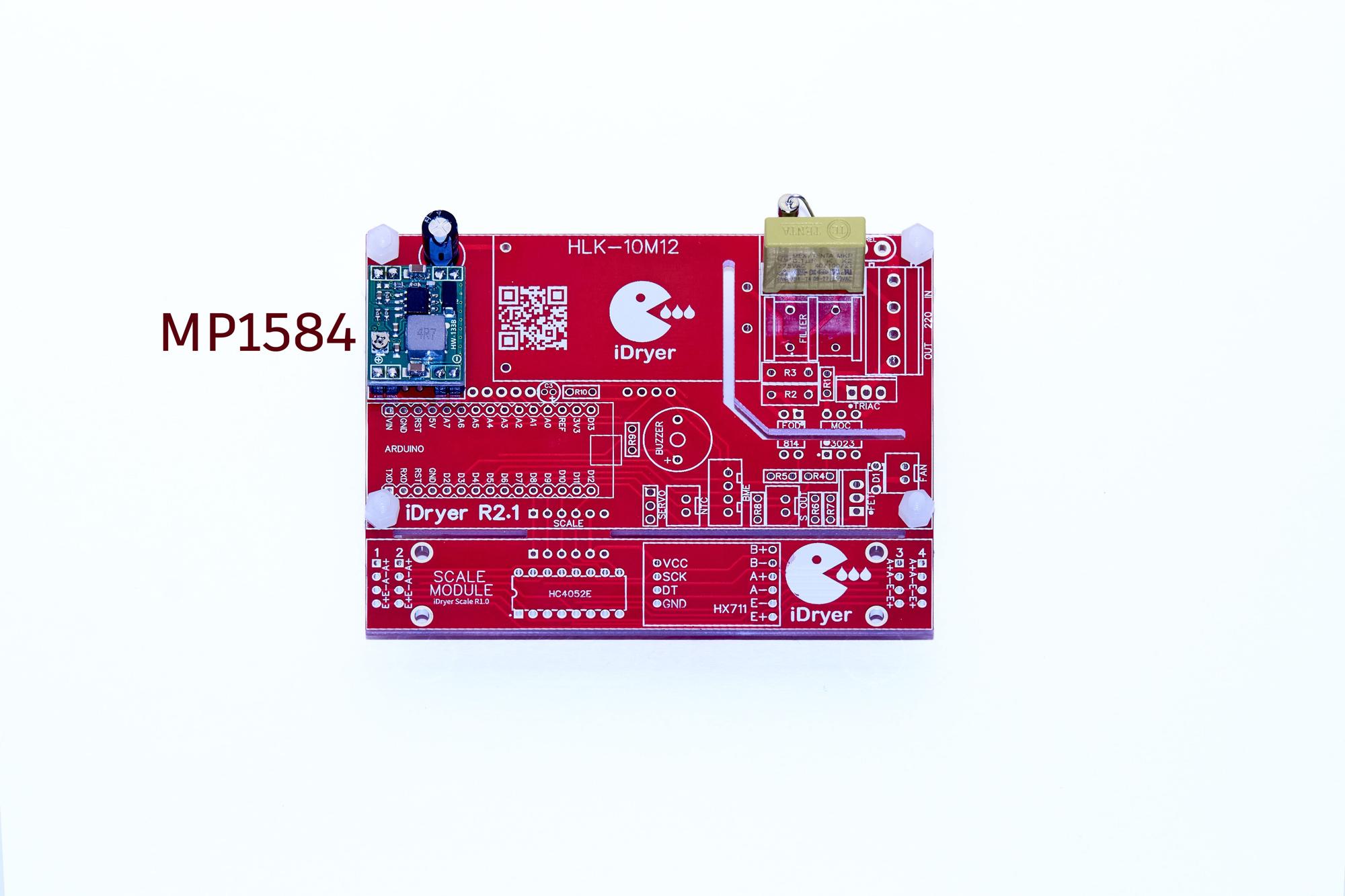
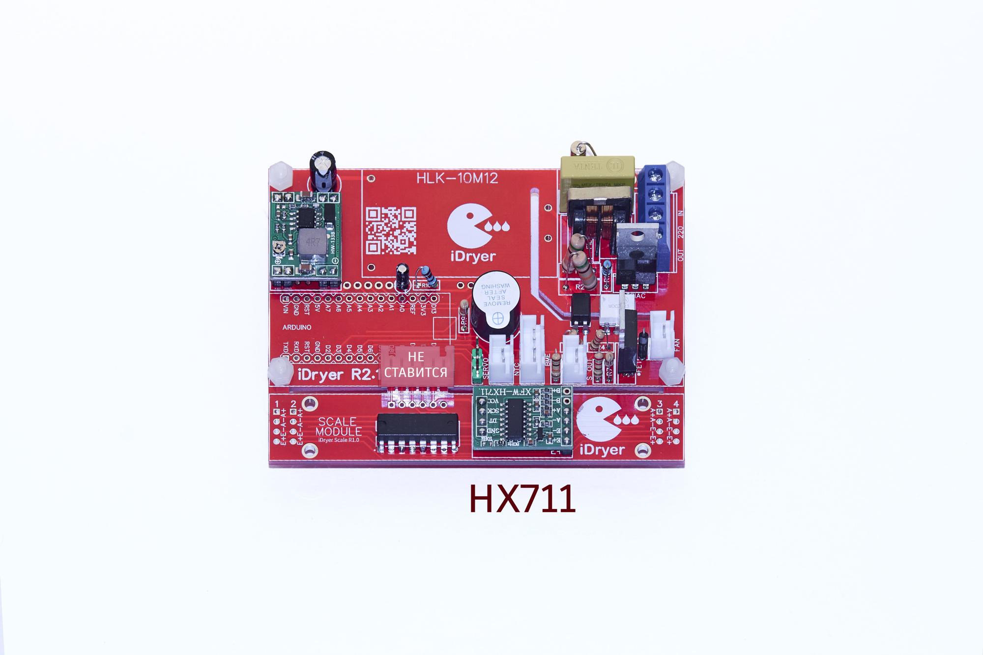
Before assembly, you must set the output voltage to 5.1V on the MP1584 converter and resolder the frequency selection resistor on the hx711
Assembly Sequence


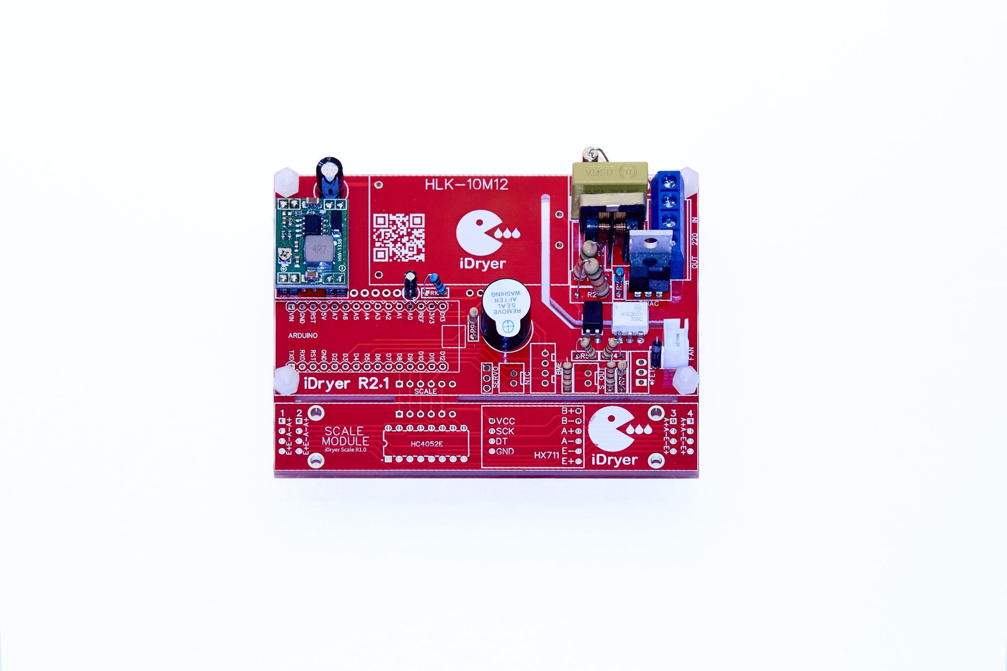

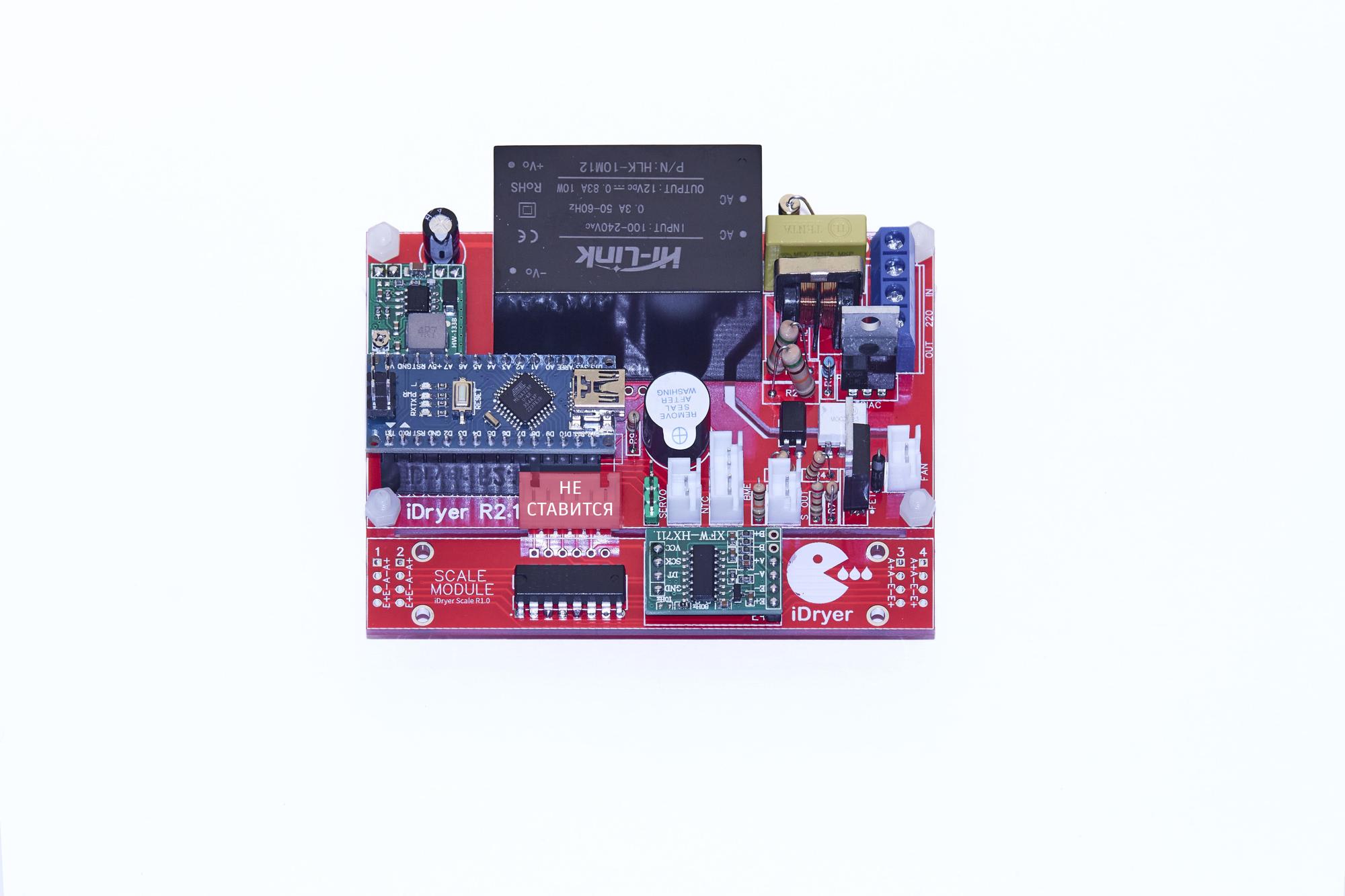
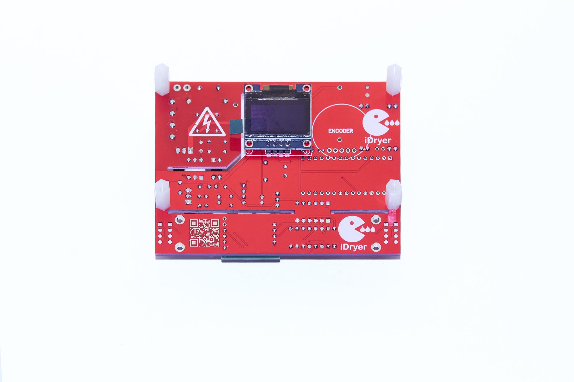
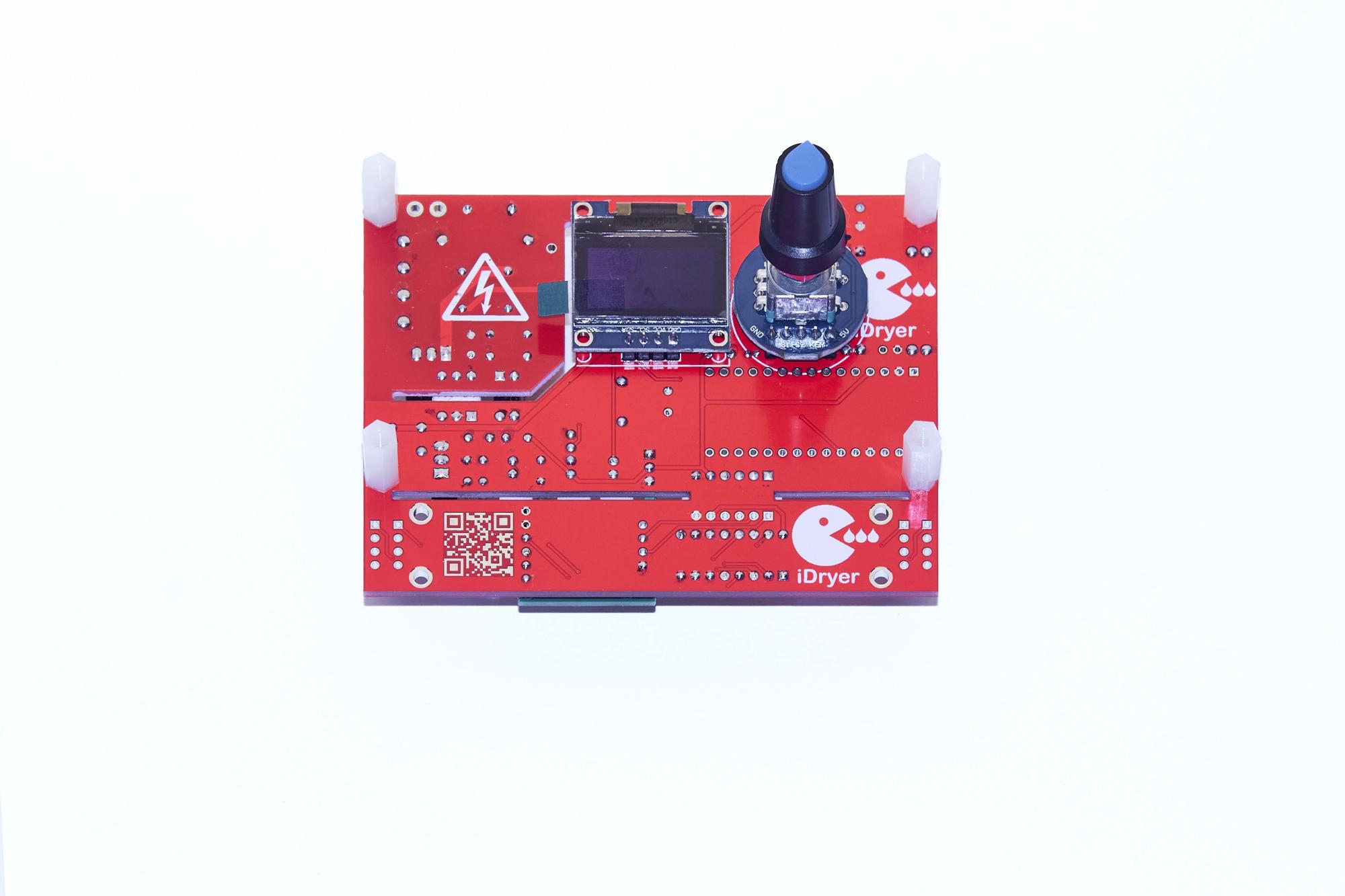
Header Pins
In the current assembly variant, header pins of 4 and 5 pins respectively are soldered to the board for connecting the display and encoder. For connection, use wires terminated on one side with BLS connectors (Dupont/black) which are soldered into the encoder and display; if necessary, the header pin installed at the factory can be desoldered from the encoder.
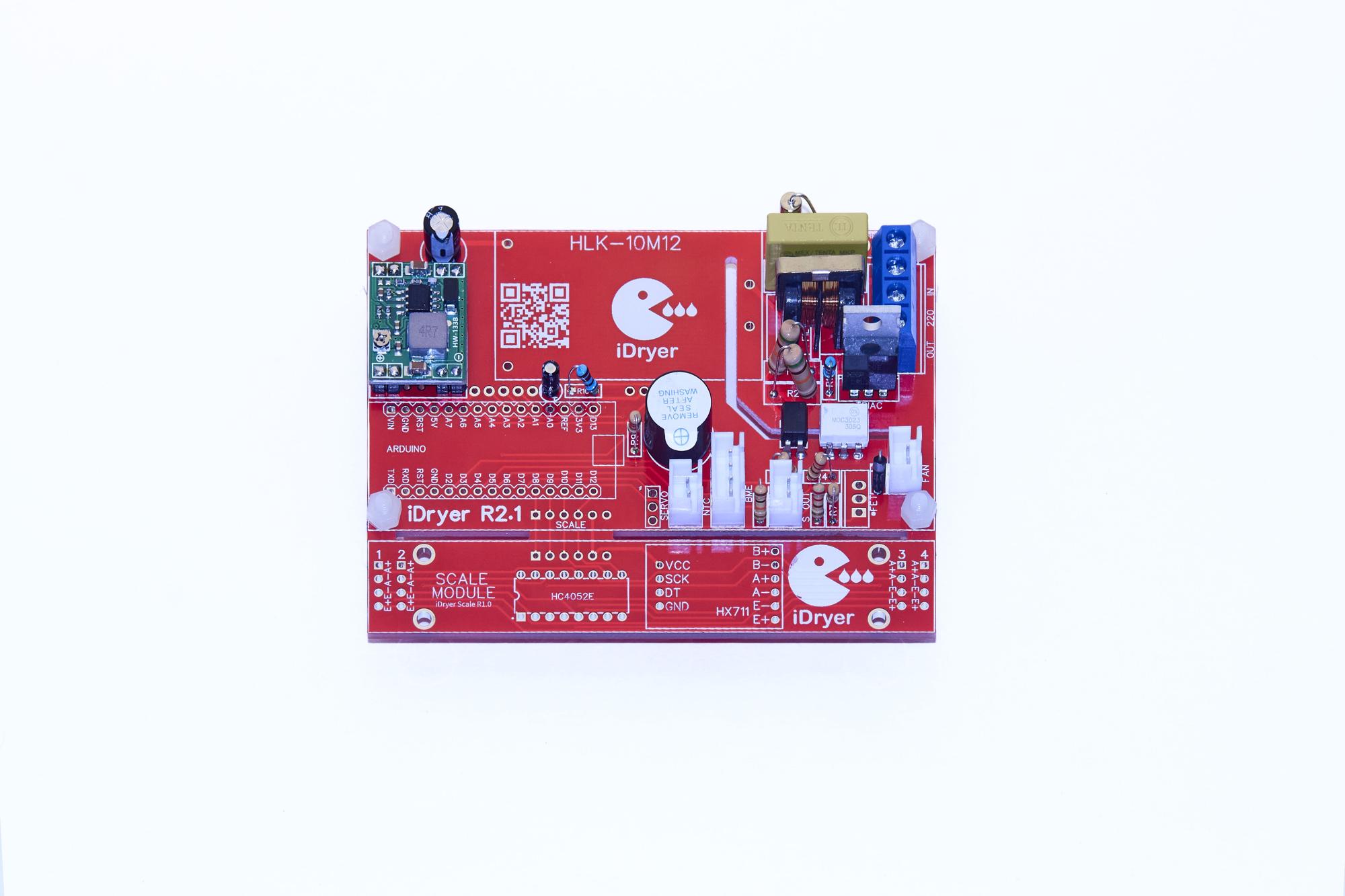
The BME280 sensor is soldered to the wires included in the kit; the wire into the sensor connector (white) into the board
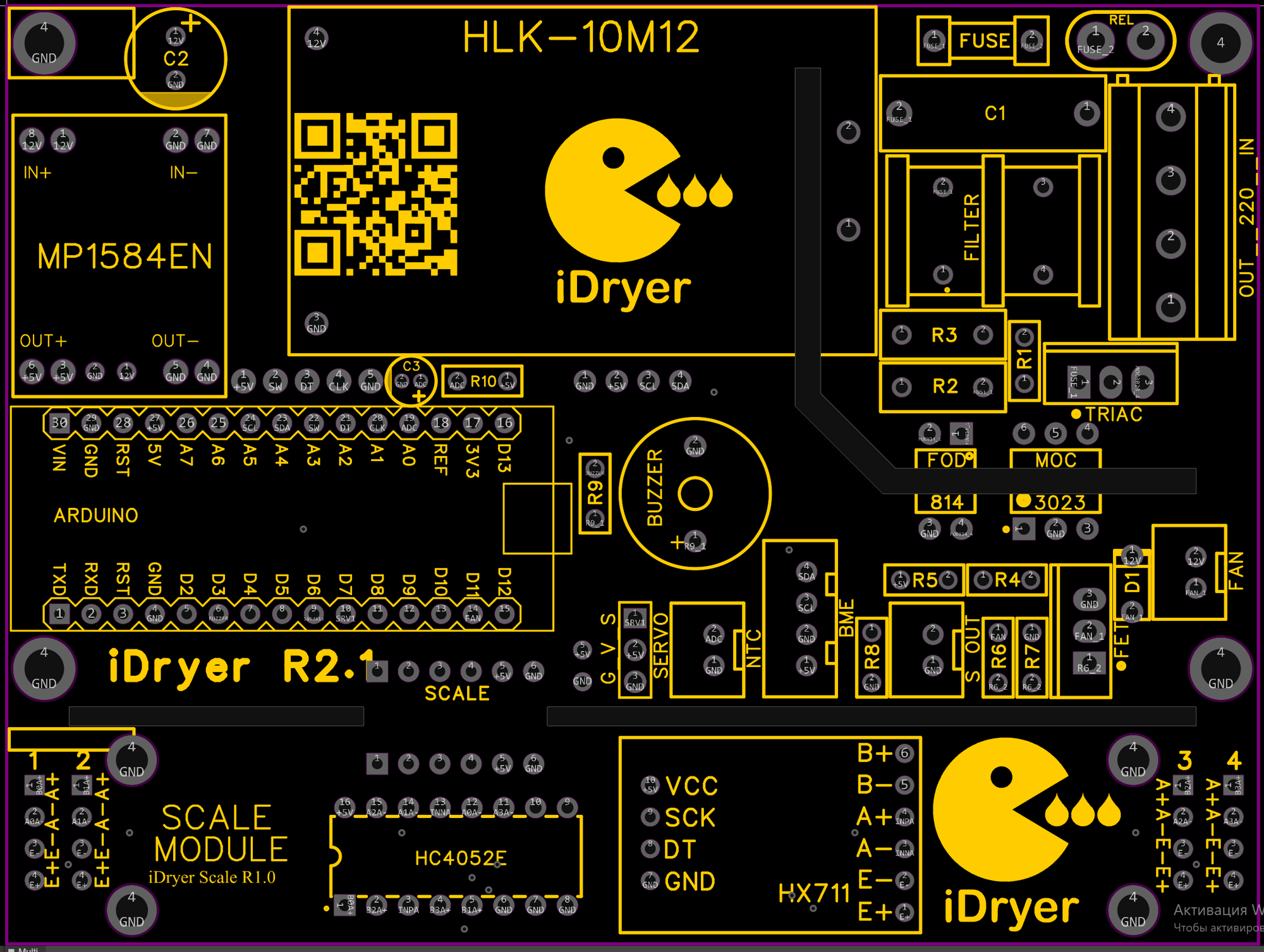
Check the orientation marks on the microchips and silkscreen
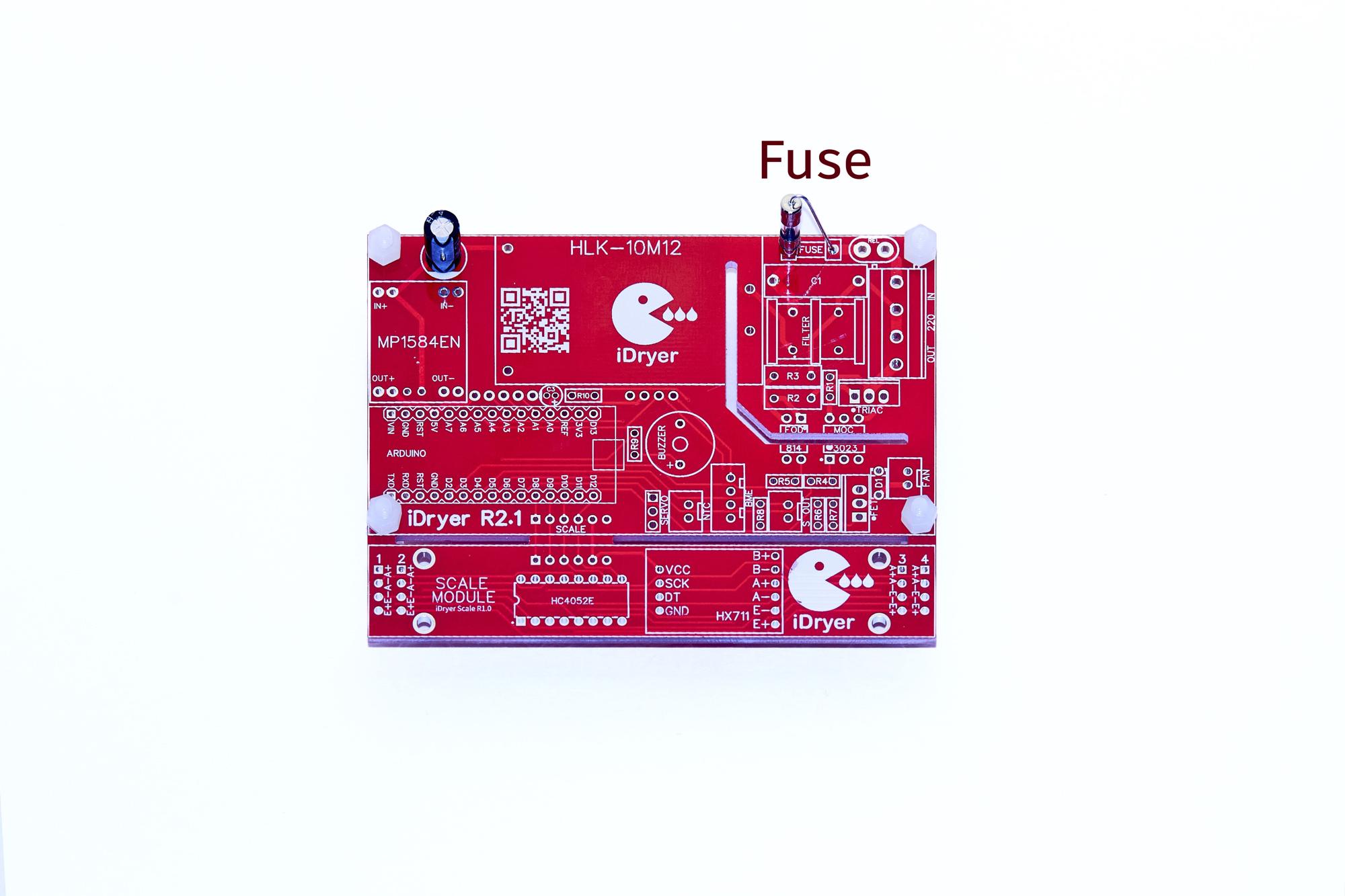
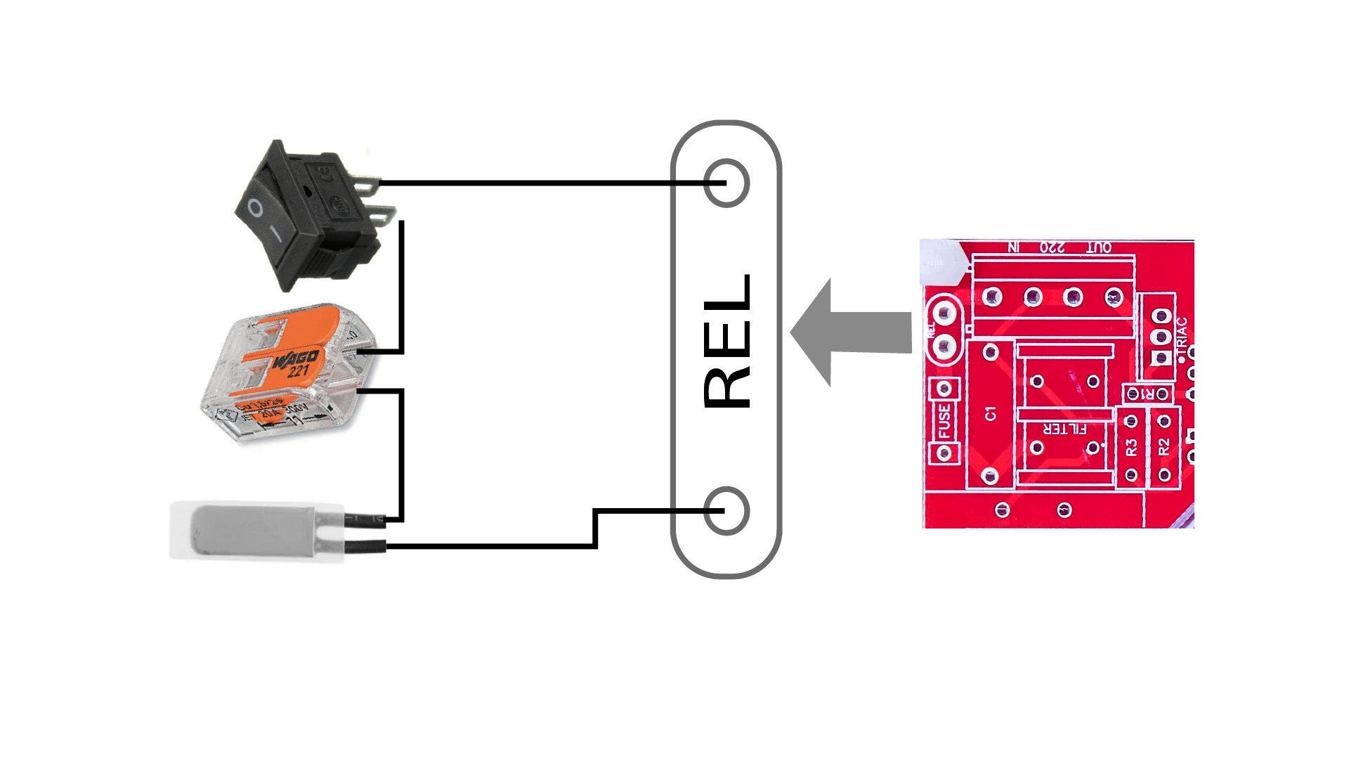
Thermal Fuse and Switch Connection
Display and Encoder Board Mount
to be done when the controller is assembled in a separate housing